More than 75% of the failures of the hydraulic system are caused by oil contamination, and the oil is inevitably contaminated in use, so the role of the filter is very large. It can remove impurities in the oil, keep the oil clean, prevent oil pollution, and ensure the normal operation of the system.
First, the main performance indicators of the filter
The performance indicators of the filter include filtration accuracy, flow capacity, working pressure, pressure drop characteristics, dirt holding capacity, service temperature, etc.
Filtration accuracy indicates the size of the largest particles removed, categorized into four levels: coarse (d≥0.1 mm), ordinary (0.1>d≥0.01 mm), fine (d≥0.005 mm), and special fine (d≥0.001 mm). In hydraulic systems, filtration accuracy must be less than half the minimum clearance of the moving parts, and higher system pressure requires greater filtration accuracy, as detailed in Table 5.1.
The filtration ratio evaluates a filter’s accuracy by comparing the number of particles larger than size x in the upstream oil to those in the downstream oil. A higher value indicates better filtration accuracy.
Second, the type and structure of the filter
The filter has four forms: mesh type, line gap type, sintered type, paper core type and magnetic type.
1. Mesh filter
It is composed of upper cover 1, lower cover 4, cylindrical skeleton 2 and fine copper wire mesh 3, etc., to remove impurity particles with a diameter of d >0.08~0.18 mm, the pressure loss does not exceed 0.01MPa, and the flow capacity is large, but the accuracy is low.
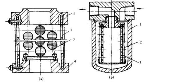
2. Linear gap filter
It is composed of a top cover 1, a shell 2, a fine metal wire 3 and a cylindrical skeleton 4, and the residual particles with a diameter of d >0.03~0.1 mm are removed, and the pressure loss is 0.07~0.35 MPa, and the flow capacity is large, but it is not easy to clean. Mesh filters and line-gap filters are surface-type filters, as shown in Figure 5.5.
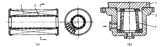
3. Paper wick filter
The core consists of plain or corrugated phenolic resin or microporous filter paper (0.35-0.75 mm thick) that filters particles of d≥0.005-0.03 mm, with a pressure loss of 0.08-0.4 MPa. While it has good filtration efficiency, it has a low flow capacity and requires frequent replacement, as shown in Figure 5.6.
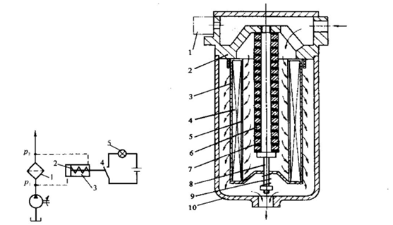
4. Sintered filter
Paper-core filters and sintered filters are depth filters. As shown in Figure 5.7, there is a filter with an alarm mode. The filter element of the sintered filter is sintered by pressing granular bronze powder, filtering out impurity particles with a diameter of d≥0.01~0.1mm, and the pressure loss is 0.03~0.2MPa.
5. Magnetic filter
Magnetic filters can absorb magnetically sensitive metal filings, iron powders or magnetic abrasives in the oil, and are often combined with other forms of filter elements to make composite filters, as shown in Figure 5.8.
Third, the selection of filters
System requirements must be met. Filtration accuracy depends on particle size: ≥ 0.1mm is a primary filter; d > 0.01mm is a normal filter; d > 0.005mm is a fine filter; d > 0.001mm is a special fine filter.
(2) There should be sufficient flow capacity. Flow capacity refers to the maximum flow rate allowed through the filter under a certain pressure drop, which should be selected in conjunction with the installation position of the filter in the system.
(3) It should have a certain mechanical strength and not be damaged by hydraulic force.
(4) Cleaning and replacement should be convenient.
(5) There are some special requirements to consider. Such as anti-corrosion, magnetic, sending, non-stop replacement of filter elements, etc.
Fourth, the installation location of the filter
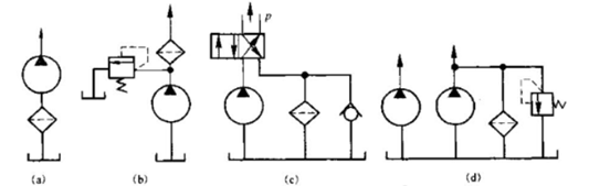
1. Installed in the suction port of the pump
For the protection of the pump, a coarse filter can be selected, but it is required to have a large flow capacity to prevent cavitation.
2. Install at the outlet of the pump
A fine filter must be selected to protect components other than the pump. It is required to be able to withstand the working pressure and pressure shock on the oil road.
3. Install on the oil return road of the system
To remove the dirt generated in the system, a filter with a low element strength can be used. In order to prevent the filter from clogging, it is generally necessary to install a safety valve in parallel or install a transmitter.
4. When the flow rate of the pump is large on the branch road of the system, in order to avoid the selection of too large filters, a small size filter is installed on the branch road
5. Installed in an independent filtration system
Through continuous circulation, the dirt in the oil is specially filtered, and the filter can only be used in one direction. The installation location of the filter is shown in Figure 5.9.