1. The function of the fuel tank
(1) Sufficient oil required by the storage system,
(2) Dissipate heat in the oil.
(3) Escape the air dissolved in the oil.
(4) Precipitate the dirt in the oil. (5) For medium and small hydraulic systems, the top plate of the oil tank is also used to install the pump device and some hydraulic components¹ stumbling
2. Classification of fuel tanks
At present, there are many manufacturers of hydraulic pumps, but most of them are designed and manufactured according to the specific requirements of users, and have not yet been fully serialized and standardized. Only the fuel tank capacity series has the national standard GB2876-1981 (L): 4, 6.3, 10, 25, 40, 63, 100, 160, 250, 315, 400, 500, 630, 800, 1000, 1250, 1600, 2000, 3 150, 4 000, 5 000, 6 000 (L), and the models are YZ, YG, YZS, YH, SE and so on.
The fuel tank can be divided into overall structure and separate structure from the structure. The former uses the cavity of the equipment body as the fuel tank, which has poor heat dissipation and inconvenient maintenance: the latter is flexible in layout and convenient for maintenance, and is usually welded with 2.5~5mm steel plates.
1-oil suction pipe: 2-net filter: 3-air filter: 4-oil return pipe: 5-top cover; 6 – Level Finger
In addition to the rectangular structure, there are also indicators: 7, 9 – Partition: 8 – The design of the oil drain plug is a round and simple horizontal structure, and the standard oval head can be welded at both ends of the rolled cylinder section, and the hole is covered at the top of the simplified body. A typical set-up of a fuel tank is shown in Figure 5.10.
3. Typical structure and design points of fuel tank
1. Determination of fuel tank volume V
The volume V of the oil tank can be estimated by taking the multiple of the rated flow rate q of the hydraulic pump
V=sqm
(5.1)
The unit of V is L, and the unit of q is L/min; The coefficient of low-pressure system is m=2~4min, the coefficient of medium-pressure system is m–5~7min, and the coefficient of high-pressure system is m=6~12 min.
In order to prevent the return of oil from spilling the tank, the oil level height should not exceed 0.8 times the height of the fuel tank.
2. Design points
(1) Base wood setting.
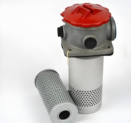
The oil tank can be provided with an oil suction filter (some do not), in order to facilitate the cleaning of the filter, the oil structure should be considered to be easy to disassemble. An air filter should be installed on the tank cover, and its ventilation flow should not be less than 1.5 times the pump flow, and the bottom of the fuel tank should be set with feet.
(2) Set up oil drain port and cleaning window.
The bottom of the fuel tank should be made at an appropriate slope, and the oil drain plug and valve should be set up to drain the oil. Large tanks should also be on the side
The surface is designed to clean the wide mouth. (3) A level gauge should be installed on the side wall of the fuel tank to indicate the highest and lowest oil levels. The inner wall of the new fuel tank should be coated with oil-resistant and anti-rust paint and anti-condensation treatment. The ruler fuel tank should be welded with corner plates and ribs to increase the stiffness.
(4) Partition setting.
The suction pipe and the return pipe should be separated by a partition to increase the distance of oil circulation and have enough time to separate the gas and precipitate impurities. The height of the bulkhead is generally 3/4 of the height of the oil level. soak
(5) Suction, return and drain pipe setting.
The distance between the suction pipe and the bottom surface of the fuel tank is H≥2D, and the distance from the tank wall is not less than 3D. In order to prevent air from being introduced, the oil return pipe should be inserted below the oil level, h≥2d away from the bottom of the tank, and the oil discharge port should be cut to 45° to increase the flow area. The drain pipe should be above the oil level.
(6) Oil temperature control.
The normal working temperature of the fuel tank is 15~65°C, and a thermometer or temperature controller and heat exchanger can be set.
(7) Large and medium-sized fuel tanks should be provided with lifting hooks or lifting holes.
In order to prevent the oil from being polluted, each cover plate and nozzle on the oil tank should be properly sealed, the oil filter should be added to the oil injector, and the air filter should be installed on the vent.